How To Wire An Outlet In Series
A How-To video on wiring an electrical outlet. Always connect the white wire to the neutral terminal of outlets and light fixtures.
Follow this procedure for all but the last outlet in the circuit.

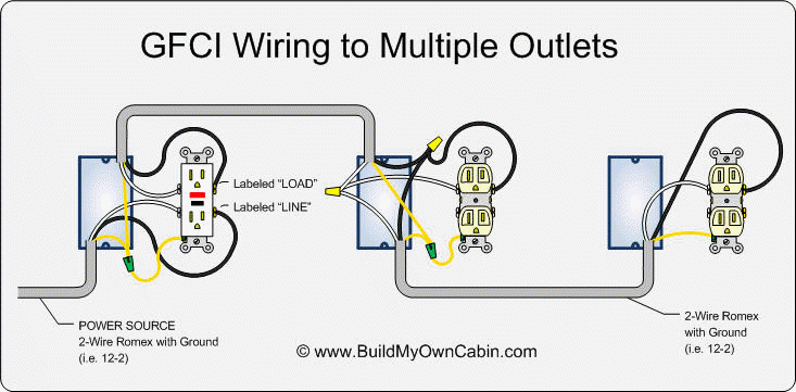
How to wire an outlet in series. They only need to be a few inches long. The red wire switched hot wire going to the outlet wires into the other side of the switch and the white wires neutral tie together to complete the return side of the circuit. However should the GFCI go bad then all the connected downstream outlets will also cease to function.
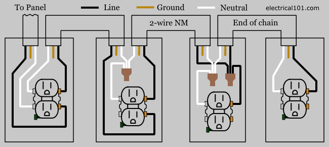
Its a good way to wire a GFCI outlet if you want outlets after it in the chain to stay on when the GFCI trips but be aware that those outlets wont have ground fault protection. White wires are to be connected to the silver terminals or screws or to the terminals marked WHITE or NEUTRAL One of these white wires brings the neutral wire of the circuit in to the electrical box and connects to the receptacle. Wiring outlets together using the device terminals instead of a pigtail splice as shown in the next diagram can create a weakest link problem.
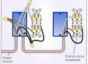
The black wire hot wire coming in from the left is the source power. Self-adjusting wire stripper - httpsamznto2. One of the most common wiring configurations your going to find with outlets are shown in the.
In this diagram wall outlets are wired in a row using the terminal screws to pass voltage from one receptacle to the next. If playback doesnt begin shortly try restarting your device. Connect the hot wire to the other terminal.
This section of the circuit then is an example of wiring in series. The neutral earth and live wire should be connected to the box. Wiring multiple outlets in seriesparallel.
To wire outlets in series youll need to cut taps theyre also called pigtails or conductors. How to wire an electrical outlet wiring diagram wiring an electrical outlet receptacle is quite an easy jobif you are fixing more than one outlet the wiring can be done in parallel or in series. Its not too difficult to wire an outlet in series.
The earth wire is usually greenyellow while the live is usually pinkred. Connect the black wires to the brass terminals on the outlet youre wiring connect the ground wires to the ground terminal then twist the white wires together and cap them. Wiring diagrams for switched wall outlets do it yourself help wiring a switch and outlet the safe easy way family handyman wiring diagram for a series of receptacles home electrical wiring diagrams double gang box do it yourself help wiring multiple gfci outlets an electrician explains how to wire a switched half hot outlet.
These are short lengths of wire. The video covers how to strip electrical wire create loops on the load neutral and ground wire and how to. Wiring GFCI Receptacles with a Protected Outlet This gfci wiring provides protection to a duplex receptacle outlet at the end of the series.
Electricians hardly ever wire outlets this way but its good to know about it because it gives you near 100-percent assurance of circuit continuity. If you wanted to ignore code and wire your outlets in series the procedure would be the same. Its usually identified by a silver or light-colored screw.
Connect the wires to the receptacles. The neutral terminal is always marked. Cut three of them one for the hot one for the neutral and one for the ground wires.
Its a good way of wiring outlets together if you want them all to work off a single switch. Videos you watch may be added to the TVs watch history and influence TV. The neutral could be white or black.
The load terminals can be used to extend wiring to additional regular receptacles beyond the GFCI which allows them to also enjoy GFCI protection. The second white wire connects the circuit neutral onwards to the next receptacle downstream from this one. Strip ½ inch of the insulation off both ends of each wire and set the wires aside.
The silver screws should be connected to the Neutral wire White or Blue The green screw should be connected to the ground earth wire GreenYellow or naked If there is no color coded screws on outlets refer to the user manual or contact a licensed electrician. Wiring Outlets In Series Diagram. By connecting the load terminals on the last gfci the wall outlet at the end is protected and can be used just as if it were one of the gfci receptacles.
But these color schematics are subject to change depending on your country. In this video I show the basic fundamentals for wiring a standard 110V electrical outlet in North America. Wiring Multiple Outlets in a Series.
 Wiring Diagram For Outlets In Series
 Gfi Wired In Series Diagram Fusebox And Wiring Diagram Device Church Device Church Id Architects It
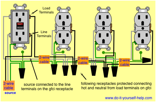 Wiring Diagrams For Multiple Receptacle Outlets Do It Yourself Help Com
 Diagram Pickups Wiring Diagram Parallel Full Version Hd Quality Diagram Parallel Diagramforgings Amministrazioneincammino It
 House Wiring Series Fusebox And Wiring Diagram Component Get Component Get Sirtarghe It
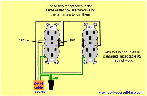 Wiring Diagrams Double Gang Box Do It Yourself Help Com
 How To Wire A Double Receptacle Two Different Ways Youtube
The Usb Outlet Works After Installing But Other Outlets And Lights Switch In The Same Room No Longer Work What Did I Do Wrong Quora
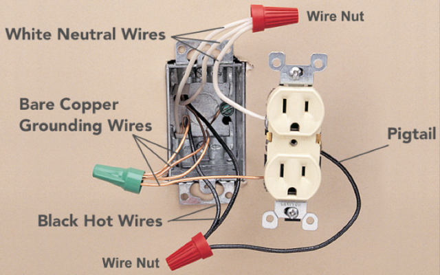 Electrical Receptacle Wiring In Parallel Vs Daisy Chained How To Wire Up A Receptacle Or Outlet Two Options Wiring Details
 How To Wire An Electrical Outlet Youtube
 Wiring Diagram For House Outlets Http Bookingritzcarlton Info Wiring Diagram For House Outlets Outlet Wiring Electrical Wiring Outlets Electrical Wiring

Comments
Post a Comment